Flex-10 ESX design with simplicity and scalability: Part 1
I’ve written quite a few posts about HP Flex-10 and some of the challenges and solutions to getting everything up and running.
I’ve also discussed my ideas about Flex-10 ESX design on the vSoup.net podcast so here it is…
If you are deploying Flex-10 make sure you have all the prerequisites in place:
http://www.wooditwork.com/2010/08/09/flex-10-esx-pre-requisites/
I also recently managed to find the manual page for the HP Virtual Connect Flex-10 10Gb Ethernet Module for c-Class BladeSystem on HP’s site which is a good reference launch page for the latest HP Virtual Connect Ethernet Cookbook and all other Flex-10 related documentation. Don’t you love trying to find things on HP’s site?
http://h20000.www2.hp.com/bizsupport/TechSupport/DocumentIndex.jsp?lang=en&cc=us&contentType=SupportManual&prodTypeId=3709945&prodSeriesId=3794423&docIndexId=64180
I do however think that HP is trying a little too hard to sell all the benefits of Flex-10 and is possibly sacrificing simplicity to show off all the features of Flex-10. They seem to want you to cram us much of Flex-10 into your deployment as possible when you should rather be streamlining the design to rather give you only what you need.
One of the goals of this blog is simplifying IT so it’s time to apply this to Flex-10.
Let’s start with how to get your chassis talking to each other.
HP c7000 Chassis’ with Flex10 switches are meant to be joined together. You can join 4 chassis together but its more common to join 3 together as it fits better in your rack. It may be a good idea to name your chassis from the bottom of the rack up starting with Chassis A because if you are starting with 2 x chassis you will have Chassis A and Chassis B and later can add another Chassis C to fill up your rack. If you have A at the top with 2 chassis, when you add Chassis C the order will be confusing.
You will have 1Gb Onboard Administrator network cables from each OA module to an upstream switch providing chassis management and iLO for your blades.
You will then cascade the OA modules together using ethernet network cables so you can manage all your chassis by connected to any one of them.
That takes care of the cabling for chassis administration.
You will then hopefully have purchased 2 x Flex-10 switches for each chassis and inserted them in Bay 1 and 2. What you want to do is link all these Flex-10 switches together with HP stack cables so they form a single logical network and traffic from blades in one chassis can travel to switches or blades in another chassis without having to go to an upstream switch.
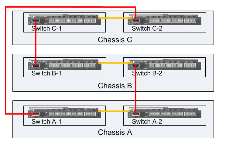
Adjacent switches in a chassis are linked together via the chassis backplain. You then need to create a ring to connect all switches together and provide 2 directions for traffic to pass. Connect 10Gb CX-4 HP Stacking cables to the X1 connector to link the chassis together.
This is what your stacking cabling will look like. Orange lines are internal stacking links and red lines are external cables. For a 3 x chassis deployment you will need 3 x CX-4 stack cables.
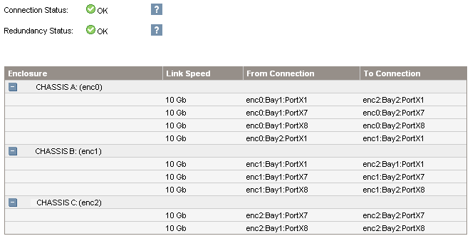
If your stacking is all correct within Virtual Connect Manager you will see the following:
You can get more chassis stacking information from HP’s Virtual Connect Multi-Enclosure Stacking Reference Guide.
Cooking with Flex-10
HP’s Virtual Connect Ethernet Cookbook:Single and Multi Enclosure Domain (Stacked) Scenarios is a good start to see what is possible with Flex-10 networking.
Although it is a comprehensive document at 229 pages, I don’t think it does a good job of helping you decide which scenario you should deploy. It does give many scenarios but without discussing the merits of each.
As I said in the beginning, I get the impression HP is trying just a little too hard to show how great Flex-10 is and sacrificing simplicity in the process so you go through the whole document and are still none the wiser as to which scenario you should go for.
The design I recommend isn’t part of the cookbook in its entirety but is actually there in parts spread across multiple scenarios.
What are you trying to achieve with your ESX networking and Flex-10?
For this design I would like to achieve the following:
- Use BL460 or BL490 blades without needing additional mezzanine cards
- Provide fault tolerant network connectivity to all ESX hosts
- Use NFS or iSCSI for storage traffic so its all ethernet and you don’t have to pay extra for fiber channel
- Have enough bandwidth available for VM Traffic, Storage Traffic, Management Traffic and vMotion traffic
- Segregate VM and Storage traffic so during normal operation they don’t share bandwidth
- Separate vMotion traffic so it doesn’t compete with VM/Storage traffic and contain the traffic within a rack keeping it more secure
- Support multiple VLANs for VM traffic
- Use all available network uplinks so you don’t waste 10GbE ports being idle or standby
- Allow easy future expansion capacity for additional networking
- Keep it simple!
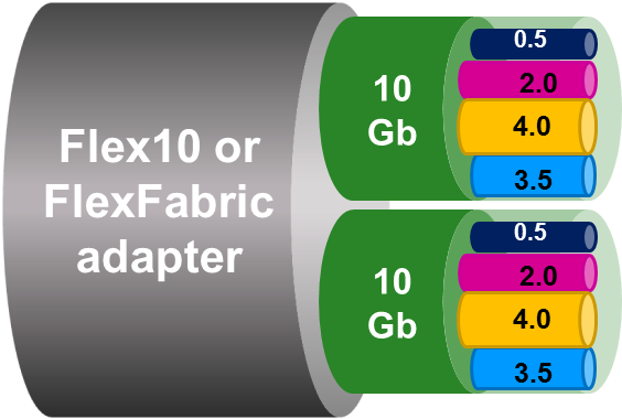 Flex-10 technology allows you to partition each of the 10GbE Nics on a blade into 4 x Nics and partition the 10GbE between the 4 x Flex-Nics, which is where the Flex(ible) part comes in. This means a BL460/490 blade with 2 onboard 10GbE Nics can see 8 x Nics. Although these Nics are logical from the Flex-10 point of view the blade sees them as 8 separate physical Nics with 8 different MAC addresses.
If you were to install Windows on a blade you would see the following devices:
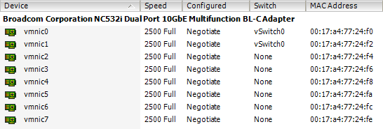
If you were to install ESX you would see the following:
Each Flex-Nic is named individually in Virtual Connect with the LOM (Lan on Motherboard) identifier and corresponds to an ESX vmnic number which will be mapped later to a Virtual Connect Ethernet Network.
| Flex-Nic | vmnic | Virtual Connect Port | Ethernet Network |
|---|---|---|---|
| LOM:1-a | vmnic0 | Port 1 | vm_trunk_1a |
| LOM:2-a | vmnic1 | Port 2 | vm_trunk_2a |
| LOM:1-b | vmnic2 | Port 3 | vm_vmotion_1b |
| LOM:2-b | vmnic3 | Port 4 | vm_vmotion_2b |
| LOM:1-c | vmnic4 | Port 5 | unused_nic_1c |
| LOM:2-c | vmnic5 | Port 6 | unused_nic_2c |
| LOM:1-d | vmnic6 | Port 7 | unused_nic_1d |
| LOM:2-d | vmnic7 | Port 8 | unused_nic_2d |
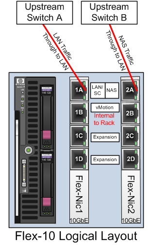
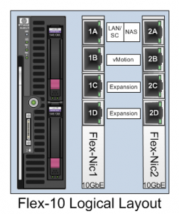 Each of these 8 x Nics is then assigned to an ethernet network that is created within Virtual Connect Manager. Some of these networks may in turn have uplinks assigned so the Flex-Nic can talk to the LAN or they may be internal to the rack. You can think of these 8 x Flex-Nics as 8 x Nics coming out of a rack mounted server and you can choose which ones get connected to upstream switches. This is what the Flex-10 logical layout looks like.
Breaking down some of the design goals we can start to see what traffic we need to support. Service Console traffic is very minimal so could be shared with VM and/or storage traffic. We need a Nic for VM traffic and we need a Nic for storage traffic. We need a separate Nic for vMotion traffic as we don’t want to risk flooding VM/storage traffic with vMotion traffic.
Looking at VM and storage traffic we need to ensure we have redundency for the network traffic. As we have a share of 10GbE available per Flex-Nic we could however create a team of 2 x Flex-Nics to provide redundency and use ESX port groups to redirect VM traffic over 1 x Flex-Nic and storage traffic over 1 x Flex-Nic but be able to use the other Nic in the pair for redundency.
We also need to provide redundency for vMotion traffic as well so that would be another 2 x Flex-Nics.
So, with 4 x Flex-Nics we can satisfy all traffic requirements.
HP’s cookbook scenarios try and use as many of these 8 x Flex-Nics as possible to show off Flex-10 but I prefer to use 4 x Flex-Nics so you have spare Nics available if in the future you need to be able to add functionality to additional networks.
The first pair of Nics, 1A and 2A, carrying VM and Storage traffic need to talk outside the rack to upstream switches. The second pair of Nics, 1B and 2B, carrying vMotion traffic don’t need to talk outside the rack as vMotion traffic doesn’t need to appear on the LAN and as it is not encrypted we also want to keep it separate from LAN traffic.
From an individual blade perspective this is what the networking will look like:
VLANs
Blades are all about a converged infrastructure. You purchase blades so you can share power and networking and make it quicker to be able to provision servers. You still however want to be able to segregate traffic and this is where port groups and also VLANs come in.
There are two operational modes for HP Virtual Connect. Mapped Mode and Tunneled Mode. Mapped Mode allow you to create Ethernet Networks and manage VLANs within Virtual Connect. Tunneled VLANs allow you to create Ethernet Network but pass through all traffic through Virtual Connect whether they are VLAN tagged or not. As ESX has very good support for VLANs this design uses Tunneled mode to pass all VLANs through the Virtual Connect switches and uses ESX networking to manage the VLANs using Port Groups.
Using Tunneled Mode also means you only need to manage your VLANs at the upstream switch. Any VLANs created on the upstream switches and trunked down the uplinks will be passed through Virtual Connect and be directly available to ESX.
This means you don’t have to create and manage the VLANs on your upstream switches as well as in your Virtual Connect Domain.
VLANs are a great way to manage network capacity. It’s a good idea to create multiple VLANs to separate different traffic. Create a VLAN for your physical host IP addresses (Service Console/Management Network and vmkernel) and multiple VLANs for your VM traffic. Plan ahead for your VM capacity and ensure you have enough IP addresses to grow into. If your VDI environment could grow into 2000 VMs then why not even double your requirement for your VLAN planning just in case you buy another company or combine two datacenters and then you don’t have to worry about adding capacity later.
So, how can we make all this happen with Virtual Connect?
First you will need to have created your Virtual Connect domain and imported all your chassis. The instructions for this are in the HP Cookbook so I won’t repeat here.
Then you need to Set the Ethernet Settings | Advanced Settings and select Tunnel VLAN Tags.
Flex-10 Networking
Next you want to create your Ethernet Networks. Create a separate Ethernet Network for each Flex-Nic so that would be 8. The reason for this is that you to be able to manage the networking for each Flex-Nic separately. Network redundency will be a function of ESX to handle failover so you don’t need to have multiple Flex-Nics connected to a single Ethernet Network to achieve this.
| vm_trunk_1a | vm_trunk_2a |
| vm_vmotion_1b | vm_vmotion_2b |
| unused_nic_1c | unused_nic_2c |
| unused_nic_1d | unused_nic_2d |
When you have created your Ethernet Networks in Virtual Connect Manager they should look like this:
This is normally the time to add uplinks to your Ethernet Networks but hold off for now as its worth explaining the link between Ethernet Networks and server profiles.
You need to connect each Flex-Nic to its Ethernet Networks which is done as part of the server profile.
Create the server profiles for each blade creating 8 x Networks Connections and then mapping the Flex-Nic LOM to the Ethernet Network Name.
Here is where you can allocate Bandwidth if you need to. I’ve just split the 10GbE evenly between the 4 x Flex-Nics. This would mean you have 2.5 Gb available for VM LAN traffic, another 2.5 Gb available for vmkernel storage traffic and 2 x 2.5 Gb available for vMotion.
I think this is plently of bandwidth. Remember your network bottleneck is unlikely to be your blade as you will be sharing 10GbE uplinks to your upstream switches between all the blades in your rack. Your NFS/iSCSI NAS Server probably has 10GbE available bandwidth and you are connecting 48 blades to this so 2.5 Gb per blade is plenty.
The same server profiles need to be created for all blades.
Now we will add the uplinks. The Ethernet Networks for LAN and NAS traffic need to be connected to the external world using a design goal to use all uplinks for traffic and not have passive 10GbE connections doing nothing.
The 6 x Flex-10 switches are acting as a single logical stacked switch. Each blade is connected to the same set of Ethernet Networks so traffic on for example the vm_trunk_1a network is passing through each Flex-10 switch through the stacking cables. This means you can connect the vm_trunk_1a Ethernet Network to uplinks from any switch in the stack.
This stacking is what allows vMotion to be contained within the rack. Every blade can see every other blade in the rack over the stacking links using the vm_vmotion_1b and vm_vmotion_2b networks without having to have any uplinks assigned.
As we are going to be using ESX port groups and ESX failover order settings to direct VM traffic and NAS traffic over separate Nics, think of your rack as being split in two vertically with LAN traffic travelling over the left hand side and NAS traffic over the right hand side.
Let’s look at the bandwidth and cabling options that are possible.
20Gb Option
The simplest design would be having 2 x 10GbE uplinks from your rack going to upstream switches. This will provide you with 20Gb total bandwidth for both LAN and NAS.
- Run a cable from the Flex-10 Switch in Chassis A Bay 1 Port X2 up to a 10GbE port on Upstream Switch 1. Through this all blade LAN traffic will be primarily directed.
- Run a cable from the Flex-10 Switch in Chassis C Bay 2 Port X2 up to a 10GbE port on Upstream Switch 2. Through this all blade NAS traffic will be primarily directed.
 Configure the upstream switch ports as trunked access ports and add all vlans you will require for your ESX hosts.
Within Virtual Connect Manager:
- Edit the vm_trunk_1a Ethernet Network and add the Uplink in Chassis A Bay 1 Port X2
- Edit the vm_trunk_2a Ethernet Network and add the Uplink in Chassis C Bay 2 Port X2
Once you have added the External Uplink Ports to your Ethernet Network ensure you enable Smart Link and Enable VLAN Tunneling.
Smart Link is the HP technology that tells an individual Flex-Nic its associated uplinks are down so a blade can use its own network teaming software to fail over network traffic. As the Flex-10 Nics are hard wired in the chassis to the Flex-10 switches they do not go down so you need something to be able to tell the Flex-10 adapter that it is not connected to the external network. Smart Link is what allows this down to an individual Flex-Nic.
Your Ethernet Networks should now look like this:
40Gb Option
If 20Gb of bandwidth will not support your needs you can easily double the bandwidth to 40GbE by running a second cable for each pair.
- Run a cable from the Flex-10 Switch in Chassis A Bay 1 Port X2 up to a 10GbE port on Upstream Switch 1. Through this all blade LAN traffic will be primarily directed.
- Run a cable from the Flex-10 Switch in Chassis A Bay 1 Port X3 up to a 10GbE port on Upstream Switch 1. Through this all blade LAN traffic will be primarily directed.
- Run a cable from the Flex-10 Switch in Chassis C Bay 2 Port X2 up to a 10GbE port on Upstream Switch 2. Through this all blade NAS traffic will be primarily directed.
- Run a cable from the Flex-10 Switch in Chassis C Bay 2 Port X3 up to a 10GbE port on Upstream Switch 2. Through this all blade NAS traffic will be primarily directed.
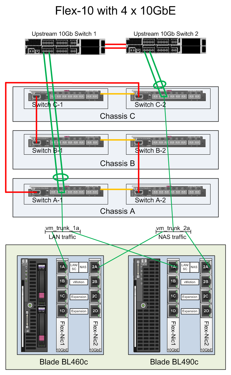 You will need to create a LACP group on each of your upstream switches and put both uplink ports into the group.
Configure the upstream switch ports within the LACP groups as trunked access ports and add all vlans you will require for your ESX hosts.
This will allow all ports to be active so you will have 40Gb available.
Within Virtual Connect Manager:
- Edit the vm_trunk_1a Ethernet Network and add the Uplinks in Chassis A Bay 1 Port X2 and Port X3
- Edit the vm_trunk_2a Ethernet Network and add the Uplinks in Chassis C Bay 2 Port X2 and Port X3
Once you have added the External Uplink Ports to your Ethernet Network ensure you enable Smart Link and Enable VLAN Tunneling.
If your LACP groups are set up correctly, you should see all uplinks as Linked-Active.
Your Ethernet Networks should now look like this:
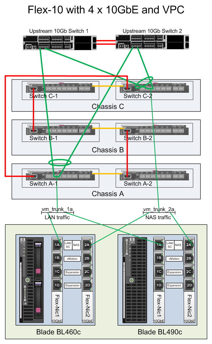
40Gb vPC Option
If you are using a Cisco Nexus series switch you can improve failover by splitting your LACP groups across the upstream switches by using a VPC. For a LACP group to be formed both uplinks need to be in the same Flex-10 Switch but with a VPC this can be in separate upstream switches.
- Run a cable from the Flex-10 Switch in Chassis A Bay 1 Port X2 up to a 10GbE port on Upstream Switch 1. Through this all blade LAN traffic will be primarily directed.
- Run a cable from the Flex-10 Switch in Chassis A Bay 1 Port X3 up to a 10GbE port on Upstream Switch 2. Through this all blade LAN traffic will be primarily directed.
- Run a cable from the Flex-10 Switch in Chassis C Bay 2 Port X2 up to a 10GbE port on Upstream Switch 1. Through this all blade NAS traffic will be primarily directed.
- Run a cable from the Flex-10 Switch in Chassis C Bay 2 Port X3 up to a 10GbE port on Upstream Switch 2. Through this all blade NAS traffic will be primarily directed.
You will need to create VPC groups for each uplink pair across both your upstream switches and put both uplink ports into the group.
Configure the upstream switch ports within the VPC groups as trunked access ports and add all vlans you will require for your ESX hosts.
Once you have added the External Uplink Ports to your Ethernet Network ensure you enable Smart Link and Enable VLAN Tunneling.
Your Ethernet Networks will be configured in the same way as the 40Gb Option.
If your VPCs are set up correctly, you should see all uplinks as Linked-Active.
In Part 2 we’ll continue and look at how the Flex-10 networking is presented and configured in ESX.






Excellent post Julian. We’re in the process of migrating our core network to 10GB and the Flex-10 options are definitely on the cards in the coming months. Knowing you’ve spelt out the ‘real world’ implications here means I’ll know exactly where to start investigating. I bet this post took a while to put together!
Really cool stuff!
I am planning on deploying some Flex10 stuff in the next few months and the one concern I have is with the stacking bandwidth in between the modules on the chassis itself, it’s just a pair of 10GbE links right? My own network design uses 2x10GbE links per flex10 module to the core switches (potentially going as high as 4 per module depending on need 10gig is really cheap in the grand scheme of things).
8 x BL685c G7 blades per chassis (48 core/512GB/server). Storage is native fibre channel (trying to give time for the flex fabric software to stabilize more). I suspect I won’t come close initially to maxing out the stacking bandwidth, but it is a fear in the back of my mind, would be much more comfortable with at least 80Gbps stacking between the modules within the chassis(be real happy if it was just line rate!)
In my ideal world things would be stacked, but nothing other than control traffic would cross the stacking links, eliminating this as a bottleneck, and the modules themselves would talk directly to the core network.
I came up with this diagram a while back:
http://yehat.aphroland.org/~aphro/virtualconnect_blade_configuration.png
Also was thinking hard about using mapped mode instead of tunneled mode, if I recall right mapped mode allows server-server communication to occur within the module itself instead of being passed to the upstream switch, but I can see the value of the tunneling mode from a management perspective and monitoring, be able to leverage the line rate sflow capabilities of the upstream switches to watch the traffic in real time.
thanks again for the great info
Everything I have read states the correlation with single VC domain and stacking enclosures, never have I seen it written that each enclosure can be it’s own domain and still do a 10G interconnect between enclosures just for VMotion.
Can this be done. We are seeing HP virtual Macs getting used in the wrong enclosure when we did this. Are we missing something?
Len, I don’t think you can do 10G interconnect between chassis in separate domains. the VC domain is what allows the traffic to flow through multiple switches.
As for MAC addresses, check whether you are using factory MACs from the individual blades or Virtual Connect assigned MAC addresses. If you are using Virtual Connect assigned MAC addresses ensure the range you select is different for every Virtual Connect domain otherwise you will get MAC address conflicts.
I have a fairly similar environment using 4 X Cisco 3021X, C7000 with NC325m Quad Port 1Gb NIC in Mezz sot 1 and Quad LoM,
I am trying to put understand:
1: how ESXi vmnics will map to the physical nics to ensure I build redundancy.
2: How to take advantage of the 3021X as it has 1, 10 GB uplinks.
I saw the mapping in the article and just wonder if it would be the same.
PS: Excellent article, much better that HP confusing long docs
@Nassif Do you mean 4 x Cisco 3120X switches. These have 1 GB downlinks to the blades.
I haven’t worked with chassis with more than 2 x 3120 switches and also mezzanine cards.
I think each blade would be presented with 4 x Gigabit Nics, the additional 1Gb ports on the mezzanine card can only be used with additional switches in the Interconnect Bays.
I think vmnic0 and vmnic1 would route through the 3120x in Interconnect Bays 1 and 2 and vmnic2 and vmnic3 would route through the 3120x in Interconnect Bays 3 and 4.
I’m not sure how the 4 x 3120x would stack together. Would it form a single logical switch?, Are the switches in Bays 1 & 2 connected to the switches in Bays 3 & 4. This may dictate how many uplinks you require.
As for redundancy you would need to work out whether you would build this into your Cisco 3120 networking topology and have failover happen at the Cisco level or take it down to your ESX level and get the ESX hosts to handle failover between the vmnics.
Hi Great Article, I have been wading through the Cook Book which as you say is a bit wordy.
We have some 3750 switches which have a 10GB option but I am not sure we could connect the C7000 @ 10GB. I am a bit unsure on the Physical connections HP say one type of cable, Cisco have a different one. I am ok with the Cisco kit do you know what cables and or SFp’s are needed?
Thanks
@Mike,
For the HP side, if you are using fiber, I think you will need an HP SFP transceiver module, 453154-B21 – HP BLc Virtual Connect 1Gb RJ-45 Small Form Factor Pluggable Option Kit
http://h30094.www3.hp.com/product.asp?sku=3742795&mfg_part=453154-B21&pagemode=ca
Nice post!
We have Cisco Nexus equipment, and Flex-10 VC’s – we are doing the same thing as your “40Gb Option” – except that each uplink set from the (2) VC’s is a vPC to a Nexus 2232->Nexus5020. As long as you use active/active SUS, and use vPC commands on port-channels you set up for uplinks, everything comes up fine. We use a 3rd party twinax cable which further reduces cost and cabling- this is a huge difference from 1Gb VC’s and 32 TP cables.
regards,
Ian
Quick question for you folks. We’re currently implementing 2 Flex10 switches in bay 3 and 4 of our c7000 chassis. I was wondering if it is possible to team a nic from each Flex10 switch, say port 1 from each switch? They will be connecting upstream to a pair of Nexus 5548’s using vPC. This would provide Flex10 switch module redundancy, as well as upstream switch redundancy. Also, could someone explain the diffrence between ports x1-6, and x7-8? I understand x7-8 are uplinks, but aren’t they all technically uplinks?
Yes, it is possible to team nic’s from each Flex-10 to increase redundancy. Have a look at this link that explains the mapping graphically: http://tinyurl.com/4yo84fj.
Ports x7-8 have additional functionality, from HP site:
“Port X7 and port X8 is internally cross linked to an adjacent HP Virtual Connect Flex-10 module. This connection is used a Stacking link (Virtual Connect Flex-10 bay 1, port X7 – Virtual Connect Flex-10 bay 2, port X7 and Virtual Connect Flex-10 bay 1, port X8 – Virtual Connect Flex-10 bay 2, port X8 ) between the Virtual Connect Flex-10 interconnects.
Port X7 and port X8 can also be used to connect to an external network switch. The moment an external SFP+ module is inserted in port X7 or port X8 , the internal stacking link (Virtual Connect Flex-10 bay 1, port X7 – Virtual Connect Flex-10 bay 2, port X7 , or Virtual Connect Flex-10 bay 1, port X8 – Virtual Connect Flex-10 bay 2, port X8 ) is disabled and not visible anymore as Stacking link within Virtual Connect Manager (VCM) “
I am running a configuration using the HP7000 chassis with 2 flex10 in bay 1 & bay 2. We have created two separate etherchannels to each bay running 20GB each. Our problem is with multicasting. We are seeing duplicate messages getting to our clustered servers within the HP chassis. When we remove one of the two Flex10 bay links, it stops. Any thoughts?
Hi Guys, like all the info and posts about this Flex-10 tech. I have a quick and maybe simple question regarding this tech. My setup is very simple 2 x c7000 with VC modules in IC bays 1 and 2 in each chassis. I have 1 x uplink from bay 1 to LAN stack and 1 x uplink to iscsi stack in each chassis. Uplinks to each stack are etherchannelled together with single vlan on each. Smartlink is enabled on HP VC. I am having to use IP HASH on ESXi 5 on vswitches. Each vswitch has 2 vnics which connect to a 1-to-1 vNet uplink (lan or iscsi). The question is, if an IC BAY VC fails, I see the correct amount of vnics fail on the respective chassis the failed VC is in (0 2 4 6 etc), however, ESXi 5 I suppose then trys to use the other vnic in the vswitch but fails to get a response which in turn hangs the datastore and any VM’s on it. In order to get these to talk correctly, I have to shutdown the uplink to Ic BAY 2 from the cisco end to get it to fail over. I’m thinking I’m doing something wrong or the setup is not quite correct. I have no SUS configured, just straight forward 1-to-1 vnets to uplinks in tunnlled mode.
thanks,
Raj.
@nate
Hello Julian – First thank you for creating this cool Blog, i have followed it for a number of years now. I always find useful information especially with regards to VMware-ESX running on HP Blade systems. I have a question for both you and Nate. Or anyone that maybe be able to chime in with their expertise and experience.
We are currently deploying HP BL685c G7 Blades – 8 per c7000 chassis. And plan to run ESXi-5-U1 on the blades. We realize that the BL685’s come with 2 dual port CNAs – which yields 4 LOMs per blade. If we carve out all of the possible bandwiths 4 per LOM then we are left with 16 Flex NICs. 2 Flex Nics will be used for FC. That leaves 14 Ethernet Flex NICs that can be presented to the ESXi5 OS.
If we present all 14 Flex NICs to ESXi5 as VMNICs are we in violation of the VMware-ESXi5 Configuration Maximum of 8 10Gbe NICs allowed to be presented to ESXi5?
Would we be in an Un-supported configuration?
Is it best to just carve out the required bandwith and only present 8 ethernet Flex NICs Max to the ESXi5 OS?
I did notice that Nate, in his diagram carved out bandwith that yielded only 8 FlexNics and therefore only 8 VMNICs would be presented to ESX.
Thanks in advance for your help. – Jorge
Hey Nate – If you get a minute can you see my post from 7/21/12 – I have some questions – Thanks – Jorge
Excellent Article
Excellent Article.
I have run into a situation wherein customer by mistake only planned and ordered two VC-Flex 10 interconnects and have 6 half height blades for the C7000. They have the LOM plus optional MEZ cards, that shoudl normally require two more VC modules, but they have already exceeded the allocated budget and cannot order these until next year.
So my question is, can we simply use the interconnect VCs in Bay 1 and Bay 3 and then LOM1 flexNics will use Bay1 and MEZ1 will use Bay 3. And using windows 2012 based LBFO teaming, resiliency can be achieved shoudl any of the Bay 1 or bay 2 based switch?
I assume that VC manager only will run into Bay 1 or will it also work / failover to the bay 3 if bay 1 and bay 3 are connected via stacked direct connect cables?
Thanks so much and I look forward to some guidance here please.
planning to implement a number of c7000 enclosures, and they have 4* Flex 10 VC modules in each. The modules are vertically stacked using the CX4 interconnect cable.
The questions:
• Does this ‘Stack’ appear as 1 Virtual Connect in terms of the network connections to it?
• we are planning to connect 1 * 10GbE FC connection to each module, so would modules 1 & 5 be configured as a single IRF stack from the switch and if so would they need to be connected to the same switch (same goes for modules 2 &6).
Thanks for your help,
I have flexfabric vs flex 10 does all the same rules apply with your designed? And can we stack more than 1 10Gb cable for more bandwidth for internal traffic?